Plastic frame anchor SHARK® UR F A4 stainless steel
Plastic frame anchor SHARK UR F stainless steel
ANC-(SHARK-URF10)-PLA-A4-WS13-10-10X80
ZEBRA


Register and access more than 75 000 products
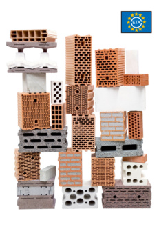
- Part of the SHARK® UR product family, which has been tested in connection with more than 100 building materials as part of ETA-08/0190!
- The SHARK® UR 8 and 10 frame anchors are tested and approved for a total of 105 different surfaces. In addition to concrete and aerated concrete, numerous bricks are included in the current most comprehensive ETA assessment, including solid and perforated brick, hollow and solid sand-lime bricks, solid and perforated concrete bricks and hollow blocks made of lightweight concrete
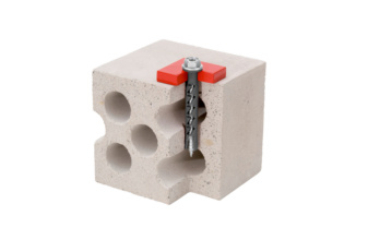
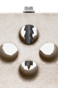
- Thanks to the ingenious anchor geometry, the "teeth" spread in four directions and claw right down into the base material
- Anchorage via friction locking between anchor sleeve and base material
- Anchor sleeve made of high-quality polyamide
- Push-through installation
- Can be loaded immediately - no waiting
- Very strong anti-rotation lock
- High load-bearing capacity thanks to expansion in four directions
- Improved load transfer through even, continuous load distribution across the entire expansion area
- The hammer-in stop prevents premature expansion of the anchor during installation
- Less installation work, as the anchor sleeve and special screw are pre-assembled
- Improved load transfer in solid and hollow construction materials
- SHARK-UR F 10 (zinc-plated steel, stainless steel): European Technical Assessment ETA-08/0190
- Expert report on fire resistance duration in the event of fire exposure
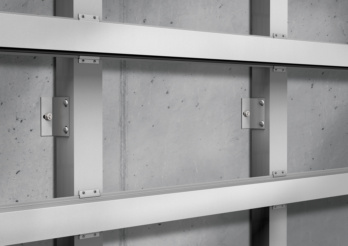 Metal substructures
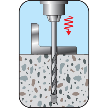
Drill the hole
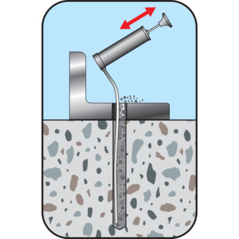
Remove drill cuttings
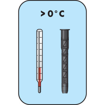
Check temperature of anchor sleeve
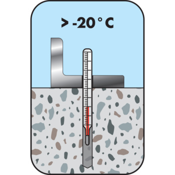
Check temperature of substrate
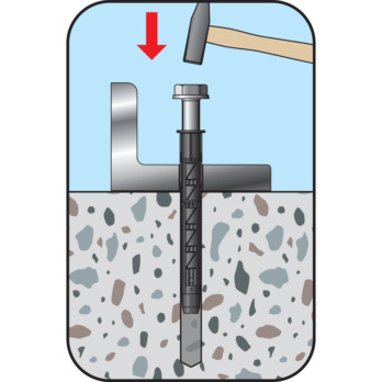
Install the anchor and screw with a hammer
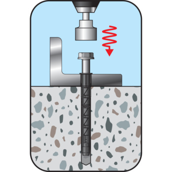
Screw in dowel
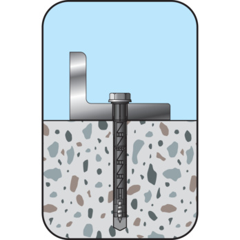
Screw in screw until flush
- SHARK-UR F 10 (zinc-plated steel, stainless steel): European Technical Assessment ETA-08/0190
- Expert report on fire resistance duration in the event of fire exposure
Datasheets(X)
- This anchor with a European Technical Assessment may be used as a fastener in a redundant non-structural system for non-load-bearing constructions (e.g., façades, suspended ceilings, etc.)
- SHARK UR, SHARK UR F can be anchored in the following anchoring substrates: Standard concrete, masonry walls (solid brick, solid sand-lime brick, vertically perforated brick, hollow sand-lime brick, hollow lightweight concrete blocks, solid bricks and blocks made of lightweight concrete, concrete bricks) and aerated concrete
- Two setting depths in defined building materials
- Installation temperatures: Temperature of anchoring base: ≥ -20°C
- Temperature of anchor sleeve: ≥ 0°C
- The stainless steel screw can be used outdoors or in damp areas
- Suitable for mounting façade, ceiling, and roof substructures (made of wood or steel), wooden beams, wooden laths, metal brackets, metal rails, suspended ceilings, cable conduits, brackets, profiles, wall-mounted cabinets, shelves, etc.
- Mountings where proof of load-bearing capacity under exposure to fire is required
- Drill perforated and hollow blocks with a rotary drill (without hammer mechanism)
- Drill cuttings must be removed from the drilling hole, e.g., with the blow-out pump art. no. 0903990001
- Drilling in concrete with a suction drill saves having to clean the drill hole
Anchor diameter | 10 mm |
Anchor length (l) | 80 mm |
Max. attachment height (t fix) | 10 mm |
Nominal drill-bit diameter (d 0) | 10 mm |
Through-hole in the component to be connected (d f) | 10.5 mm |
Fire resistance rating | F30 |
Material of screw | Stainless steel A4 |
Surface of the screw | Plain |
Head type | Countersunk head |
Drill hole depth (h 1) | 80 mm |
Approval | ETA-08/0190 |
Type description | W-UR F 10 A4, hexagonal bolt |
| Zinc-plated steel | ||||
| A4 stainless steel | ||||
| 1) The partial safety factors of the resistances regulated in the approval and a partial safety factor of the effects of γF = 1.4 have been taken into account. For the combination of tensile and transverse loads, please refer to ETAG 020 Appendix C 2) Maximum long-term temperature 3) Maximum short-term temperature | ||||
| Normal weight concrete solid brick Vbn, EN771-3, DIN 18152 | ≥ NF (≥ 240 x 115 x 71) | ≥ 2.0 | 10 | 0,43 |
| 20 | 0,71 | |||
| 28 | 1,00 | |||
| Vertically perforated brick HLz6), EN 771-1, DIN 105-1 e.g. Wienerberger, Schlagmann | ≥ 2DF (≥ 240 x 115 x 113) | ≥ 1.2 | 8 | 0,21 |
| 12 | 0,26 | |||
| 20 | 0,43 | |||
| Vertically perforated brick POROTON S11-36.56), EN 771-1, Z-17.1-812 Wienerberger, Schlagmann | ≥ 248 x 300 x 249 | ≥ 0.6 | 6 | 0,26 |
| Vertically perforated brick POROTON S11-36.56), EN 771-1, Z-17.1-812 Wienerberger, Schlagmann | ≥ 248 x 356 x 249 | ≥ 0.9 | 6 | 0,57 |
| Hollow sand-lime brick KSL6), EN 771-2, DIN 106-1 e.g. Xella | ≥ 2DF (≥ 240 x 115 x 113) | ≥ 1.6 | 10 | 0,57 |
| 12 | 0,71 | |||
| 16 | 0,71 | |||
| ≥ 8DF (≥ 249 x 240 x 238) | ≥ 1.4 | 10 | 0,26 | |
| 12 | 0,34 | |||
| 16 | 0,43 | |||
| Hollow block made of lightweight concrete 3K Hbl, EN 771-3, DIN 181516) e.g. Liapor | ≥ 16DF (≥ 498 x 240 x 238) | ≥ 0.7 | 2 | 0,10 |
| 4 | 0,26 | |||
| 6 | 0,34 | |||
| Hollow block made of lightweight concrete Liapor-Super-K6), EN 771-3, Z-17.1-501 | ≥ 16DF (≥ 495 x 240 x 238) | ≥ 0.8 | 2 | 0,17 |
| 4 | 0,34 | |||
| Aerated concrete AAC | 2 | 0,14 | ||
| 7 | 0,85 | |||
| 2) Maximum long-term temperature 3) Maximum short-term temperature 4) For other types of stone, raw densities, minimum pressure strength or temperature ranges, please refer to the approval ETA-08/0190 5) The stone geometry should be compared with the approval ETA-08/0190 6) If the drill hole is created through impact or hammer action, the permissible load must be determined by tests on the structure | ||||
| Plain concrete solid brick Vbn, EN771-3, DIN 18152 | ≥ NF (≥ 240 x 115 x 71) | ≥ 2.0 | 10 | 0,57 |
| 20 | 0,86 | |||
| 28 | 1,29 | |||
| Vertically perforated brick HLz6), EN 771-1, DIN 105-1 e.g. Wienerberger, Schlagmann | ≥ 2DF (≥ 240 x 115 x 113) | ≥ 1.2 | 8 | 0,21 |
| 12 | 0,34 | |||
| 20 | 0,57 | |||
| Vertically perforated brick POROTON T8-306), EN 771-1, Z-17.1-982 Wienerberger, Schlagmann | ≥ 248 x 300 x 249 | ≥ 0.6 | 6 | 0,26 |
| Vertically perforated brick POROTON S11-36.56), EN 771-1, Z-17.1-812 Wienerberger, Schlagmann | ≥ 248 x 356 x 249 | ≥ 0.9 | 6 | 0,43 |
| Hollow sand-lime brick KSL6), EN 771-2, DIN 106-1 e.g. Xella | ≥ 2DF (≥ 240 x 115 x 113) | ≥ 1.6 | 10 | 0,43 |
| 12 | 0,57 | |||
| 16 | 0,71 | |||
| ≥ 8DF (≥ 249 x 240 x 238) | ≥ 1.4 | 10 | 0,34 | |
| 12 | 0,43 | |||
| 16 | 0,57 | |||
| Hollow block made of lightweight concrete 3K Hbl, EN 771-3, DIN 181516) e.g. Liapor | ≥ 16DF (≥ 498 x 240 x 238) | ≥ 0.7 | 2 | 0,09 |
| 4 | 0,17 | |||
| 6 | 0,26 | |||
| Hollow block made of lightweight concrete Liapor-Super-K6), EN 771-3, Z-17.1-501 | ≥ 16DF (≥ 495 x 240 x 238) | ≥ 0.8 | 2 | 0,17 |
| 4 | 0,34 | |||
| Aerated concrete AAC | 2 | 0,21 | ||
| 7 | 0,88 | |||
| 2) Maximum long-term temperature 3) Maximum short-term temperature 4) For other types of stone, raw densities, minimum pressure strength or temperature ranges, please refer to the approval ETA-08/0190 5) The stone geometry should be compared with the approval ETA-08/0190 6) If the drill hole is created through impact or hammer action, the permissible load must be determined by tests on the structure | ||||
| Zinc-plated steel | ||||
| A4 stainless steel | ||||
| 1) The partial safety factors of the resistances regulated in the approval and a partial safety factor of the effects of γF = 1.4 have been taken into account. For the combination of tensile and transverse loads, please refer to ETAG 020 Appendix C 2) Maximum long-term temperature 3) Maximum short-term temperature | ||||


