Screw anchor W-SA
Screw anchor W-SA steel zinc plated type S
ANC-(W-SA/S)-WS24-(A2L)-10-16X80


Register and access more than 75 000 products
- Anchoring by positive locking
- Through-hole mounting
- Immediate load-bearing capacity – no waiting
- Almost no expansion effect, enabling minimal edge and axial clearance to be maintained
- Quick, easy installation or dismantling by screwing the screw anchor in and out of the drill hole
European Technical Approval ETA-05/0012: Option 1 for cracked and non-cracked concrete
Fire resistance (anchoring base: concrete from C20/25 to C50/60): R30, R60, R90, R120: Technical report TR 020 "Evaluation of anchorages in concrete concerning resistance to fire" (included in ETA-05/0012)
W-SA 16x80/10 and W-SA 20x100/10 unapproved

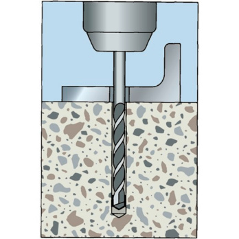
Create the drill hole
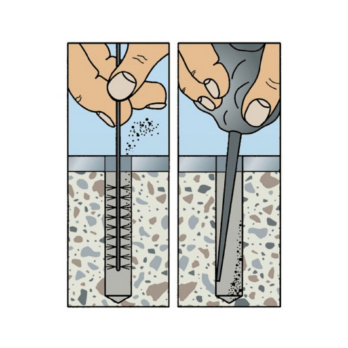
 Clean the drill hole

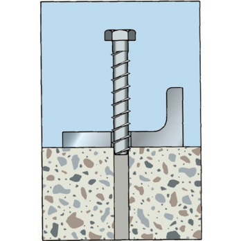
Position anchor

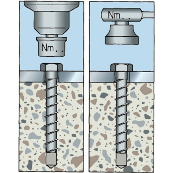
Screw in anchor and apply torque
European Technical Approval ETA-05/0012: Option 1 for cracked and non-cracked concrete
Fire resistance (anchoring base: concrete from C20/25 to C50/60): R30, R60, R90, R120: Technical report TR 020 "Evaluation of anchorages in concrete concerning resistance to fire" (included in ETA-05/0012)
Datasheets(X)
Individual attachment: Cracked and non-cracked concrete
With a European Technical Approval, the anchor may be used in reinforced or non-reinforced standard concrete of a strength class of at least C20/25 and at most C50/60 in accordance with EN 206: 2000-12
The anchor may be used for anchoring with predominantly static loads (e.g. tare weight, fittings, stored materials) or quasi-static loads (e.g. façades, railings)
Can be used in concrete < C 20/25 and hard natural stone (unapproved)
W-SA (galvanised steel) can be used in dry indoor areas
Suitable for attaching metal structures, metal profiles, brackets, footplates, supports, cable conduits, pipes, railings, wooden structures, roof beams, etc.
The saw-tooth threads cut into the concrete when the anchor is screwed into the pre-drilled hole
Head type | Hexagon head |
Nominal drill-bit diameter (d 0) | 14.0 mm |
Surface | Zinc plated |
Through-hole in the component to be connected (d f) | 18.0 mm |
External drive | WS24 |
Material | Steel |
Drive type | Hexagon |
| Performance data | ||||||||
| Anchor diameter [mm] | 7,5 | 10 | 12 | 14 | 16 | 20 6) | ||
| Admissible centric tension load1) on an individual anchor without the influence of the edge distance | Tensile zone (cracked concrete C20/252), s ≥ 3 hef c ≥ 1.5 hef) | Nadm [kN] = C20/25 2) | 2,0 | 3,6 | 4,8 | 7,9 | 11,7 | - |
| Compressive zone (uncracked concrete C20/252), s ≥ 3 hef c ≥ 1.5 hef) | 3,0 | 4,8 | 6,4 | 11,9 | 15,9 | Frec. 11.0 | ||
| Admissible shear load1) on an individual anchor without the influence of the edge distance | Tensile zone (cracked concrete C20/252), c ≥ 10 hef) | Vadm [kN] = C20/25 | 3,3 | 7,6 | 12,4 | 17,1 | 23,3 | - |
| Compressive zone (uncracked concrete C20/252), c ≥ 10 hef) | 3,3 | 7,6 | 12,4 | 17,1 | 23,3 | - | ||
| Admissible bending moment | Madm [Nm] | 9,0 | 18,1 | 39,0 | 62,9 | 103,3 | - | |
| Admissible load when exposed to fire (R30, R60, R90, R120) see European Technical Assessment ETA-05/0012 | ||||||||


